Table of Contents
1.What Exactly is an OTDR?
Have you ever wondered what makes fiber optic networks so reliable? Behind every seamless connection and high-speed data transfer, there’s a silent guardian at work: the Optical Time Domain Reflectometer, or OTDR. From my perspective, an OTDR is more than just a piece of equipment; it’s a vital diagnostic tool in the world of fiber optic communication. It helps us understand the health of our fiber networks by sending out light pulses and analyzing the reflections and scattering that come back. Think of it as a sonar for light, mapping out your fiber cable with incredible precision.
2. What Can an OTDR Do for Your Network?
Why is an OTDR indispensable for fiber optic professionals? We’ve seen firsthand how an OTDR can transform network troubleshooting and maintenance. Its core functionalities provide a comprehensive overview of your fiber infrastructure.
- Precise Fiber Length Measurement: How long is that fiber optic cable, really? Our OTDR can tell you! By calculating the time it takes for a light pulse to travel back and forth, and knowing the speed of light within the fiber, an OTDR can determine the exact length of your optical fiber, often with meter-level accuracy.
- Comprehensive Loss Detection: Are you losing signal strength? An OTDR helps pinpoint exactly where.
- Total Link Loss: It analyzes the slope of the Rayleigh scattering curve to quantify the overall signal attenuation across the entire fiber link. This tells you if your network is performing efficiently.
- Splice/Connector Loss: By looking at the difference in loss between adjacent events, an OTDR can evaluate the quality of fusion splices or mechanical connections. This is crucial for maintaining signal integrity.
- Accurate Fault Localization: Where’s that break in the line? This is where an OTDR truly shines. Using the strong signal peaks from Fresnel reflections, it precisely locates issues like fiber breaks, excessive bends, or faulty connectors. We’ve seen it pinpoint problems with less than a meter of error, saving countless hours of manual searching.
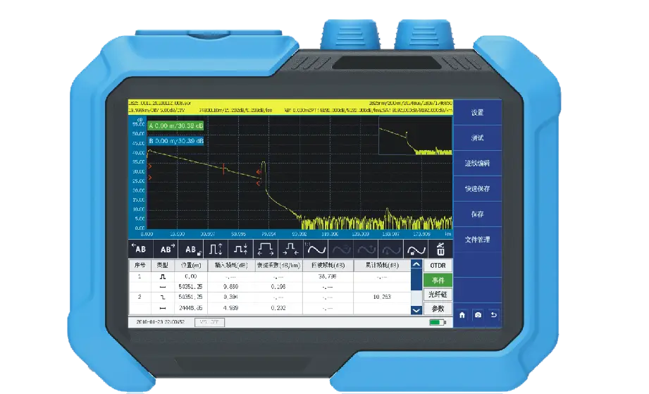
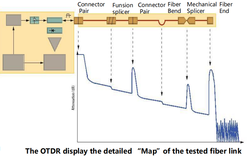
- Detailed Event Analysis: What’s happening inside your fiber? An OTDR goes beyond just finding faults. It identifies all significant events along the fiber link, such as splice points, splitters, and mechanical connections. It then generates a comprehensive event list and a loss distribution map, giving you a complete picture of the fiber’s characteristics.
3. Are You Maximizing Your OTDR's Potential? Key Parameters Explained
What critical parameters should you understand when using an OTDR? Understanding an OTDR’s key parameters is crucial for accurate and efficient testing. Let’s delve into what matters most.
Dynamic Range
What is Dynamic Range? Dynamic range represents an OTDR’s “reach” and “sensitivity.” It quantifies the difference between the strongest and weakest optical signals an OTDR can detect. A higher dynamic range means the OTDR can test longer fibers and detect weaker reflections, which is particularly important for long-haul networks. For example, G-Link’s advanced monitoring systems can feature a dynamic range of up to 50dB, capable of testing fiber links up to 200km.
Is a Larger Dynamic Range Always Better? While a larger dynamic range allows for greater test distances, it’s not always a case of “the bigger, the better.” From a practical standpoint, we always advise our clients to choose an OTDR whose dynamic range matches their actual network requirements. Opting for an excessively high dynamic range for short-distance applications can lead to unnecessary costs. For FTTx or LAN applications, a 28-38dB dynamic range might suffice, whereas for long-haul trunk lines, we’d recommend 40dB or higher.
Blind Zones (Dead Zones)
What are Event Dead Zone and Attenuation Dead Zone? Blind zones are crucial for understanding an OTDR’s ability to see closely spaced events.
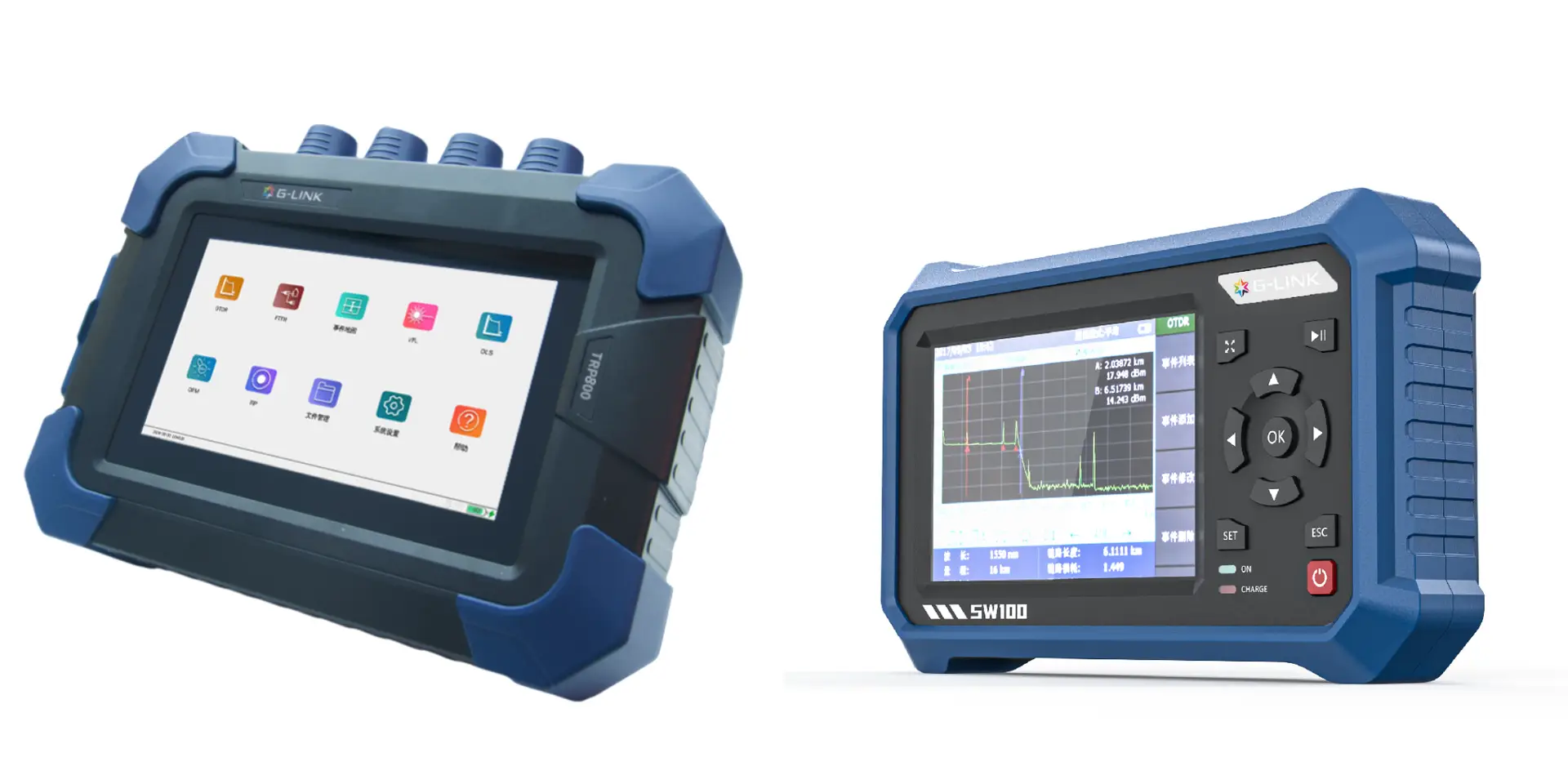
- Event Dead Zone: This is the minimum distance after a reflective event that an OTDR can distinguish another event. A short event dead zone, like the 1.2m of our TRP800 or the exceptional sub-1-meter dead zone of our TR700, is vital for scenarios with many closely spaced connectors, like in data centers.
- Attenuation Dead Zone: This is the minimum distance after a reflective event where the OTDR can accurately measure the loss of a subsequent event.
Wavelength Selection
Why are Different Wavelengths Important?
- 1310nm: Primarily used for short-distance testing and general fiber characterization.
- 1550nm: Ideal for long-distance testing due to lower attenuation in this window.
- 1625nm (or 1650nm): Often used for “in-service” or “live fiber” testing, as it allows for testing without disrupting active traffic, a feature available in select G-Link models.
Pulse Width
How do you balance blind zone and test distance? This is a classic trade-off in OTDR testing.
- Wide Pulse (e.g., 10240ns): Enhances dynamic range for longer test distances but increases blind zones.
- Narrow Pulse (e.g., 5ns): Reduces blind zones for higher resolution but limits the testable distance.
Our Suggestion: For short-distance, high-density scenarios (like data centers), prioritize a low blind zone by using narrower pulses. For long-haul lines (exceeding 80km), use wider pulses. G-Link OTDRs offer a wide range of pulse widths to perfectly balance these needs for any scenario.
| Parameter | Definition | Impact on Testing | G-Link's Recommendation |
|---|---|---|---|
| Dynamic Range | Max. signal strength difference detectable | Determines max. test distance | Match to link length: 28-38dB for short/medium links, 40dB+ for long-haul |
| Event Dead Zone | Min. distance between detectable reflective events | Crucial for closely spaced connectors | <2m for high-density applications |
| Attenuation Dead Zone | Min. distance for accurate loss measurement after reflection | Affects precision of loss measurement | Typically 5-15m, dependent on pulse width |
| Wavelength | Light wavelength used (e.g., 1310nm, 1550nm, 1625nm) | Tailored for different applications (distance, live fiber) | Multi-wavelength for versatility; 1625nm for live testing |
| Pulse Width | Duration of emitted light pulse | Affects dynamic range (wide) and blind zones (narrow) | Adjust based on scenario: narrow for resolution, wide for distance |
4.Troubleshooting with Your OTDR: Common Questions Answered
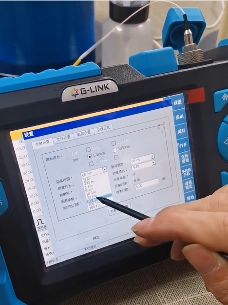
How Do I Set Up My OTDR Test Parameters Correctly?
- Wavelength: Use 1310nm and 1550nm for single-mode fiber. Use 850nm and 1300nm for multi-mode fiber.
- Pulse Width: For long-distance tests, use a wider pulse (e.g., 10240ns). For high resolution, use a narrower pulse (e.g., 5ns).
- Dynamic Range: Select based on the estimated loss of the fiber link, ensuring it’s sufficient to cover the entire length.
Why Do My Test Results Show “Blind Zones”? Blind zones are an inherent characteristic of OTDR technology. To minimize them, use the narrowest possible pulse width for your test distance. Bidirectional testing (testing from both ends) can also provide a more complete picture.
My Test Data is Unstable. What’s Going On?
- Root Cause No. 1: Contaminated Fiber End-Faces (70% of cases!): Tiny dust particles or smudges on your fiber connectors are the most frequent culprits. Cleanliness is paramount.
- Root Cause No. 2: Incorrect Parameter Settings: Trying to measure a long-distance fiber with a short pulse width will lead to unstable, noisy data.
- Root Cause No. 3: Uncalibrated Equipment: An OTDR needs regular calibration to maintain accuracy.
Single-Mode vs. Multi-Mode OTDR: How Do I Choose?
- Single-Mode OTDRs: Used for long-haul networks, typically operating at 1310nm and 1550nm. G-Link’s TR600, TR700, and TRP800 series are excellent examples.
- Multi-Mode OTDRs: For LANs or data centers with shorter runs, using 850nm and 1300nm wavelengths. Our TR600 series offers multi-mode configurations to meet these needs.

5. Choosing Your Perfect OTDR: A Scenario-Based Selection Guide
Are you overwhelmed by the choices when selecting an OTDR? Here’s how we help clients find the perfect fit, considering G-Link’s product range:
How to Choose the Right OTDR Type for Your Scenario?
- Fiber Network Installation & Acceptance: For new deployments, you need to measure length, loss, and ensure splice quality.
- Our Advice: Look for a portable, multi-function OTDR.
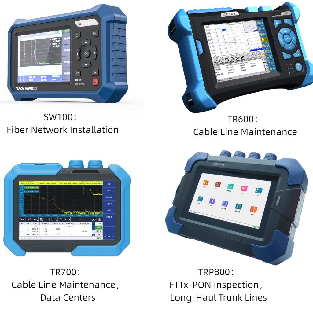
- G-Link Products: Our SW100 series is a multi-function installation and maintenance OTDR, perfectly suited for these tasks with integrated functions like a power meter and VFL.
- Cable Line Maintenance & Troubleshooting: When a fault occurs, speed and accuracy in locating the issue are paramount.
- Our Advice: Prioritize a very small dead zone, large dynamic range (30-45dB), and rugged design for field use.
- G-Link Products: The TR600, TR700, and TRP800 series are robust, high-performance portable OTDRs. The TR700, with its IP65 dust/waterproof rating and large touchscreen, is a field technician’s best friend.
- Fiber Optic Cable Inspection & Testing (Lab/High-End PON): For detailed analysis of complex networks like FTTx-PON.
- Our Advice: Opt for an OTDR with high dynamic range and advanced analysis features.
- G-Link Products: Our TRP800 series is a PON Network-specific tester, engineered to troubleshoot through splitters up to 1×128, making it ideal for detailed FTTx network inspection.
- Data Centers: These environments have dense fiber connections, requiring precise measurement of short segments.
- Our Advice: High resolution and an extremely small event dead zone are crucial.
- G-Link Products: The TR700 series excels here, featuring an event dead zone as low as 0.8 meters, which is critical for resolving closely spaced connectors and patch cords.
- Long-Haul Trunk Line Testing: For extended distances, dynamic range is your primary concern.
- Our Advice: The OTDR must have a large dynamic range (40-45dB or higher).
- G-Link Products: The TRP800 series, with its powerful 45/45/43dB dynamic range options, is ideal for accurately testing even the longest and most critical trunk lines.
OTDR Selection Priority Guide
| Scenario | Key OTDR Features Required | Recommended G-Link Product Series |
|---|---|---|
| Fiber Network Installation | Multi-function, Portable, Easy to use | SW100 series |
| Cable Line Maintenance | Fast Test Speed, Small Dead Zone (<2m), Large Dynamic Range (30-45dB) | TR600, TR700 series |
| FTTx-PON Inspection | High Dynamic Range, Ability to test through splitters | TRP800 series |
| Data Centers | Extremely Small Event Dead Zone (<1m), High Resolution | TR700 series |
| Long-Haul Trunk Lines | Large Dynamic Range (40-45dB+), Long Test Distance | TRP800 series |
6. What Should You Pay Attention to During OTDR Testing?
What are the critical do’s and don’ts when using an OTDR? A few simple precautions can make a world of difference in the accuracy and safety of your measurements.
- Avoid Strong Light Reflection: Always ensure that unconnected fiber ends are capped. Strong reflections can damage the OTDR’s detector.
- Check for Live Signals: Before testing, check if the fiber is active. G-Link OTDRs feature a communication light detection function that protects the instrument from damage.
- Regular Calibration is a Must: Adhere to the manufacturer’s suggested calibration schedule to maintain accuracy.
Can an OTDR Replace an Optical Power Meter? This is a common misconception. The answer is a firm no. An OTDR locates faults and characterizes the link, while an optical power meter measures the total end-to-end power loss. Many G-Link OTDRs, like the SW100, include a built-in optical power meter (OPM) function, giving you the best of both worlds in one device.
7. What's Next for OTDR Technology?
What exciting advancements are shaping the future of OTDRs? The field is constantly evolving, and I’m particularly excited about these trends:
- Intelligence and Automation: The integration of AI is revolutionizing data analysis, with features like one-click testing and automatic report generation becoming standard. This significantly reduces human error.
- Embedded OTDR (eOTDR): This is a game-changer for network monitoring. Embedding OTDR functionality directly into network equipment enables real-time, in-service monitoring of fiber links. G-Link is active in this area with our TMS400 Automatic Monitoring System.
- Multi-Wavelength and High Resolution: Future OTDRs are moving towards synchronous testing across multiple wavelengths and even higher resolution, enhancing the ability to analyze event details within the fiber.
8. Where Are OTDRs Commonly Used?
Where does an OTDR truly make a difference?
- Fiber Network Construction and Acceptance: Verifying installation quality, measuring fiber lengths, and ensuring splices meet performance standards.
- Fault Troubleshooting: Quickly and accurately locating fiber breaks, tight bends, or other physical damage to allow for swift repairs.
- Maintenance Testing: Regular attenuation checks to monitor the health of fiber links over time, preventing critical outages.
- FTTH (Fiber to the Home) Deployment: Verifying the integrity of last-mile fiber connections to ensure high-quality broadband service.
9. OTDR vs. OLT: What's the Difference and Why Does it Matter?
Have you ever confused an OTDR with an OLT? It’s a common point of confusion. Let’s clarify their distinct purposes.
| Attribute | OTDR (Optical Time Domain Reflectometer) | OLT (Optical Line Terminal) |
|---|---|---|
| Primary Role | A diagnostic instrument for testing the physical integrity of a fiber link. | Core network equipment that manages data transmission in a PON network. |
| Deployment | Temporarily connected for testing, maintenance, or fault-finding. | Permanently installed in an operator's central office or data center. |
| Functionality | Measures distance, loss, and reflections by analyzing backscattered light. | Converts signals, allocates bandwidth, and controls user-end ONU devices. |
| Key Use | Fiber installation acceptance, fault location, and proactive maintenance. | Providing FTTH broadband access, enterprise private lines, and 5G fronthaul. |
Should you require more detailed technical specifications or operational guides for our OTDR products, I highly recommend visiting our product pages. Have a specific project in mind?
Request a Personalized Consultation with our fiber optic experts today and let us help you find the perfect testing solution for your needs!