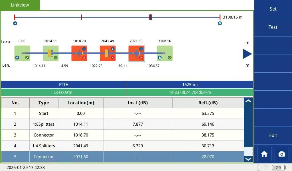
An Automatic Optical Cable Monitoring System (FAMS/TMS400) is a centralized remote testing platform that utilizes RTUs (Remote Test Units) and OTDR technology to scan fiber networks 24/7. It automatically detects, locates, and alerts operators to breaks, bends, and attenuation in real-time, significantly reducing MTTR (Mean Time to Repair) without interrupting live traffic.
Table of Contents
How Does an Automatic Fiber Monitoring System Work?
In our 15 years of experience working with telecom carriers across Southeast Asia and the Middle East, I’ve seen how natural factors like high humidity, floods, and even seismic activity can degrade fiber cables long before they actually snap. Traditionally, you wouldn’t know there was a problem until a customer complained.
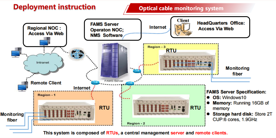
With G-Link’s TMS400 system, we’ve shifted the paradigm from reactive to proactive. The system uses a centralized FAMS Server that controls multiple RTUs (Remote Test Units) stationed at key nodes. These units perform periodic or “on-demand” OTDR scans. If the system detects a deviation from the “standard reference curve,” it immediately triggers an alarm.
Can You Monitor Live Traffic Without Service Disruption?
One of the most frequent questions we receive from CTOs is: “Will the testing signal interfere with my customers’ data?” G-Link’s Automatic Optical Cable Monitoring System ensures that testing never interferes with your revenue-generating data.The answer depends on the wavelength choice. Based on the G-Link FAMS Solution, we categorize monitoring into two distinct methods:
- Dark Fiber Monitoring (1550nm): We use the spare (dark) fibers in your cable. Since no data is traveling on these cores, we use a 1550nm wavelength to get high-precision data over long distances.
- Online (Lit Fiber) Monitoring (1625nm/1650nm): This is where our expertise shines. By using a WDM (Wavelength Division Multiplexer), we combine the 1625nm test signal with your 1310/1550nm business data. Because the wavelengths are different, they never “touch,” allowing us to monitor your network’s health while your users stream high-definition video without a glitch.
What are the Core Components of the G-Link TMS400 System?
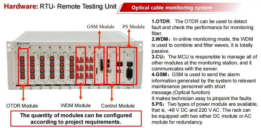
To build a robust monitoring infrastructure, you need hardware that scales. We always tell our clients to look at the Equipment Frame capacity first. Below is the ordering guidance we provide at G-Link to help you choose the right RTU size:
Ordering Guidance for your Automatic Optical Cable Monitoring System
| No. | Item | P2P (Standard) | P2P (Monitor Online) | Capacity Remark |
| 1 | Equipment Frame | 1U / 2U / 4U | 1U / 2U / 4U | 1U: 32Ch, 2U: 128Ch, 4U: 144Ch |
| 2 | MCU Board | Included | Included | Main Control Unit for RTU |
| 3 | Power Board | AC 220V / DC -48V | AC 220V / DC -48V | Dual redundancy for high reliability |
| 4 | OTDR Board | 1310 or 1550nm (30-45dB) | 1625 or 1650nm (30-44dB) | Dynamic selected basde on Shor,Medium,Long Range |
| 5 | WDM Board | – | 1625nm / 1650nm | Optional for testing in live only |
Why Should Operators Invest in Proactive Fiber Maintenance?
Many operators search for “Fiber monitoring cost” and wonder if it’s worth it. From our perspective, the ROI is found in MTTR (Mean Time to Repair). Investing in an Automatic Optical Cable Monitoring System is no longer an option but a necessity for Tier-1 carriers.
In our internal case studies, we’ve seen carriers reduce their MTTR from 8 hours down to 4 hours. How? Because the system doesn’t just say “there is a break”; it points to the exact GPS coordinate on a GIS Map. Instead of sending a technician to drive along a 50km route looking for a fallen pole, you send them directly to the spot where the damage occurred.
Key Maintenance Challenges We Solve:
- Stress Deterioration: Identifying bends caused by wind or ice before the fiber breaks.
- Water & Moisture: Detecting attenuation spikes in manholes due to poor sealing.
- Construction Damage: Real-time alerts when a backhoe accidentally hits a buried cable.
Conclusion: Partnering with a National-Level Lab
Your fiber network is the nervous system of your digital economy. Are you waiting for it to fail, or are you monitoring its pulse?
Experience the precision of the G-Link Automatic Optical Cable Monitoring System. At G-Link, we aren’t just a manufacturer; we are a subsidiary of the 34th Research Institute of CETC. We bring 50 years of national-level optical research to every RTU board we ship.
Imagine a world where 90% of your fiber faults are located before the customer even notices a drop in signal. That is the reality of the TMS400 Optical Cable Automatic Monitoring System.
Ready to protect your infrastructure? [Contact our Engineering Team] today for a customized topology design and a quote tailored to your network scale.
FAQ
Q: Can the system integrate with my existing NMS?
A: Yes, G-Link supports SNMP, SMTP, and SMS protocols for seamless integration into your existing Network Operations Center (NOC).
Q: How accurate is the fault location?
A: Using our high-precision OTDR boards, the localization error is typically less than ±10 meters plus the distance error, depending on the fiber length and GIS map accuracy.